
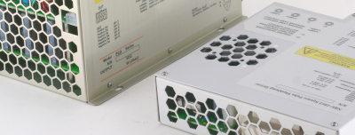

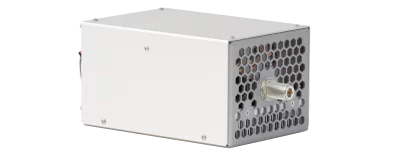
NBD-0505-PWM discharge circuit


Applications
- Discharge circuit for flashlamp operation
Features
- Flashlamp voltage – up to 500 V
- Flashlamp current – up to 500 A
- Pulse width – from 0.5 ms to 100 ms
- Max. average power – 2 kW
 Download manual (0.8 MB)
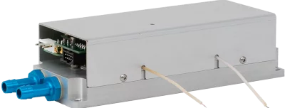
NBD-0505-PWM discharge circuit is designed for simplification of solid-state laser systems development. It is intended for use in high power IPL and long pulse Nd:YAG, KTP, Alexandrite laser systems and utilizes PWM (pulse-width modulation) technology. The module forms rectangular or quasi-rectangular pulses on a flashlamp (using energy stored in an external capacitor bank) and provides simmer current during the interval between pulses.
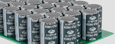
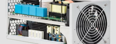
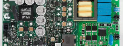
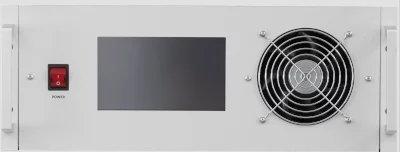
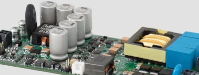
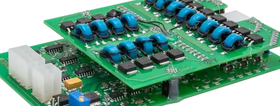
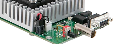
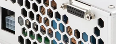
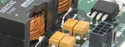
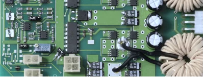
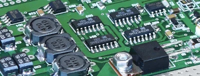
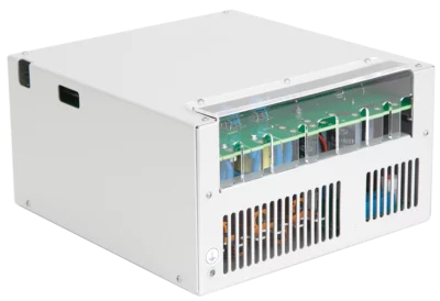
The NBD-0505-PWM consists of IGBT, its driver, protective circuits, integrated inductance coil (80 uH) and small capacitor bank (~ 1 mF / 800 V) as well as simmer and trigger circuits, discharge resistors and controls. It also contains a fan for active cooling.
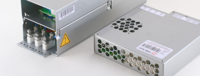
The module has two outputs by default, one is for PWM operations, the other is for free-discharge operations (can not be used simultaneously). As an option, it is possible to make one universal output for both free-discharge and PWM operations, realized as operating regimes in this case.
The flashlamp operating frequency and pulse duration is to be varied by +5 V TTL signal from an external control device applied to the respective pin.
By default, NBD-0505-PWM utilizes serial triggering method in both channels (external triggering option is available on request).
The unique feature of NBD-0505-PWM is advanced current control provided by PWM technology, which makes true rectangular pulses possible (see the picture below for a typical waveform).

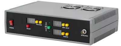
Let us emphasize, NBD-0505-PWM discharge circuit is not a stand-alone solution. For proper operation it requires capacitor charging power supply and capacitor bank, an external control device, external +24 V DC power supply, as well as other minor parts and controls (see also the picture below).

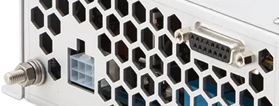
Input:
Note: module already has ~ 1 mF / 800 V capacitor bank
Output #1 (PWM):
Output #2 (Free discharge):
Simmer parameters:
Triggering parameters:
Parallel or both on request
10 kV / ~160mJ negative to LAMP-
Parallel, on request
Environment:
Other:
Modifications
Model
Description
two outputs – one for true-rectangular pulses (PWM), the other for quasi-rectangular pulses (Free discharge)
Example
one output, but two regimes of operations, one with true-rectangular pulses (PWM), the other with quasi-rectangular pulses (Free discharge)
Download user manual (0.8MB)