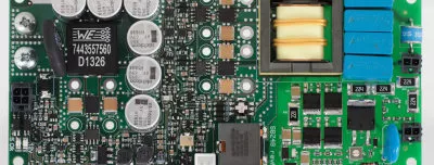
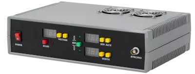
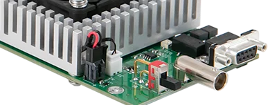
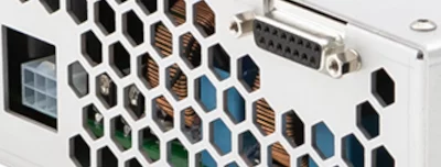
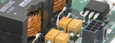
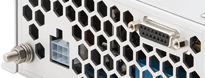
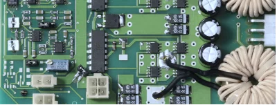
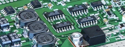
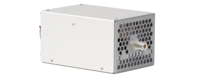
LSCB control board
Applications
- Flashlamp driving (lasers and IPL)
Controlled devices and functions
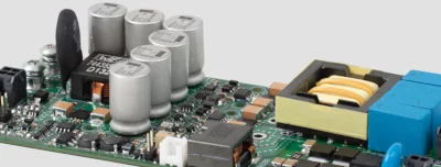
- One capacitor charger from PCA-series
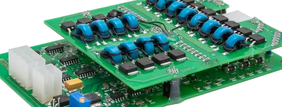
- One or two NBU-1012 discharge circuits (four channel version is available on request)
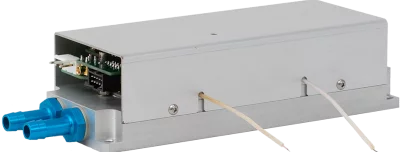
- One Pockels cell driver from QBD- or QBU-series
- Full set of minor features (IDC, footswitch, synchro input and outputs)
- RS-232 or RS-485 machine interface, PC software
The LSCB is a control board developed to simplify the design and use of flashlamp drivers based on OEM Tech’s power modules. It allows users to set and change an output voltage value for the capacitor charger and Pockels cell driver. The LSCB module also allows the user to form the output pulses for discharge circuit(s) and Pockels cell driver with user-defined delays and to vary other parameters. It is possible to synchronize the output signals either internally or externally.
By default, the LSCB controls single or dual-channel laser or IPL system with average power from 1 kW to 4 kW level. A four-channel version of the LSCB specially designed for high-power multi-channel Holmium (CTH:YAG) systems and having 8 kW maximum power capability is available on request.
Normally, the control board supports the following devices:
- One capacitor charger from PCA-series
- One or two NBU-1012 discharge circuits
- One Pockels cell driver from QBU- or QBD-series
- Full set of minor features like IDC, footswitch, synchro input and outputs
Modifications
Besides, several customized modifications of LSCB are available upon request (see also How to order? section):
- “4 channel” version – for high-power multi-channel Holmium lasers (it is able to control up to four flashlamps and synchronize their flashes with the rotating mirror)
- “PWM” version – for Nd:YAG, Alexandrite and IPL systems with long and truly rectangular pulses (it works with PWM-based discharge circuits from NBD-series)
- “Pico” version – for picosecond Nd:YAG lasers used in aesthetics (in addition to the standard equipment it is able to control a seed-oscillator driver)
- “RF” version – for aesthetic machines combining flashlamp (laser, IPL) and RF technologies (in addition to the standard equipment it is able to control an RF power module from RFGM-series)
- “Diode” version – for aesthetic machines combining flashlamp (laser, IPL) and diode technologies (in addition to the standard equipment it is able to control a diode driver of PDD-series)
The common interface to connect the LSCB to a PC or master control board is the RS-232. We supply a simple PC software together with the module. An RS-485 interface, as well as other variations, are available on request.
Please, take a look at FLD-KIT, a set of modules, which could be combined into a 1 kW to 4 kW (up to 8 kW on request) power supply for a pulsed flashlamp. We offer also several standard sets for definite systems (in the “Options” section of FLD-KIT).
Power:
Interfaces:
RS-232 (by default), RS-485 (upon request)
2x synchro outputs
Environment:
Other:
There are several modifications of LSCB in dependence on output connectors and application.
- “4 channel” version – for high-power multi-channel Holmium (CTH:YAG) systems
- “PWM” version – is suitable to work with the NBD-0505-PWM, for Nd:YAG, Alexandrite and IPL systems with long and truly rectangular pulses
- “Pico” version – for picosecond laser systems (for example, Nd:YAG)
- “RF” version – designed for an RF machines with handheld applicators
- “Diode” version – for diode machines with handheld applicators
Modifications
Modification / description
Part number
Controlled equipment
LSCB
LSCB-4
- 1pc PCA-series capacitor charger (*)
- 1-4pcs NBU-1012 discharge circuits
LSCB-PWM
- 1pc PCA-series capacitor charger (*)
- 1-3pcs discharge circuits from NBD-series (with PWM) or NBU-1012 (free discharge)
LSCB-Pico
LSCB-RF
- 1pc PCA-series capacitor charger (*)
- 1-2pcs NBU-1012 discharge circuits
- 1pc RFGM-series RF power supply
LSCB-PDD
The LSCB has an additional hardware protection from too long flashes caused by MCU failure. In other words, the maximum allowed pulse width may depend on hardware configuration. Please let us know the desired protection level at the moment of order by adding the corresponding suffix to LSCB’s part number:
- 1ms – hardware protection limits the maximum pulse width at 1ms level
- 10ms – hardware protection limits the maximum pulse width at 10ms level
- 100ms – hardware protection limits the maximum pulse width at 100ms level
- XXms – other level (XX milliseconds)
Examples:
LSCB-1ms – standard LSCB, 1ms maximum pulse width
LSCB-PWM-20ms – PWM version of LSCB, 20ms maximum pulse width
Download user manual for LSCB controller board and PC software (1.1 Mb)
Download STEP model for LSCB (ZIP archive, 36 MB)


